Wiring and nodes
Basic wiring
The central element of wiring in manim-eng is the Wire class. It takes a
start terminal and an end terminal, and automatically plans a path between the two. It
actually does this continuously via an updater, so if the terminals to which the wire is
attached are moved, the wire will plan a new path seamlessly.
class WireBasics(Scene):
    def construct(self):
        r1 = Resistor().shift(LEFT)
        r2 = Resistor().shift(RIGHT)
        self.add(r1, r2)
        self.add(Wire(r1.right, r2.left))
        self.wait()
        self.play(
            r1.animate.shift(UP),
            r2.animate.shift(DOWN),
        )
       self.play(
            r1.animate.shift(LEFT),
            r2.animate.shift(RIGHT),
        )
        self.play(Rotate(r2, angle=-PI))
        self.wait()
Planning wire paths
In order to determine what path a wire should follow, manim-eng follows the following principles:
Wires only run horizontally or vertically;
Terminals are treated as having the nearest cardinal direction (e.g. a terminal at 60° anticlockwise from the horizontal would be treated as pointing up);
Wires should never go ‘backwards’ out of a terminal;
Wire should, where possible, come out of the front of a terminal; and
Where three line segments are required, the middle segment should be placed in the middle (meaning the other two segments have the same length).
In general, the only situation in which this will produce results that look visibly strange is if two collinear terminals pointing in the same direction are connected, as demonstrated in the example below.
class StrangeAutomaticWiring(Scene):
    def construct(self):
        r1 = Resistor().shift(LEFT)
        r2 = Resistor().shift(RIGHT)
        self.add(r1, r2)
        self.add(Wire(r1.right, r2.right))

Note that these are both resistors (i.e. the right-hand one is not a fuse!)
Advanced wiring: using nodes
A notable deficiency of the Wire class is that it can only connect two
terminals. To produce more complex layouts that include intersections, we have to turn
to the Node class.
Nodes behave a little differently to normal components, namely in the way they handle terminals. Nodes can have terminals in any direction, and create them as and when they’re needed. Node terminals are only visible when wires are attached to them, and are otherwise invisible. [1]
Attaching and detaching wires
In order for a terminal to change its visibility based on whether or not a wire is
attached to it, it needs to know whether or not a wire is attached. This brings us to
the attach() and detach() methods.
These methods instruct a wire to tell the terminals it has in its start and end
attributes that it is now attached, by calling the
_increment_connection_count() or
_decrement_connection_count() methods on them.
But why not attach automatically?
It comes down to animations. Consider the following example:
n1 = Node().shift(LEFT)
n2 = Node().shift(RIGHT)
w = Wire(start=n1.right, end=n2.left)

self.add(n1, n2)
self.wait()
self.add(w.attach())
self.wait()
If Wire called attach() automatically in its constructor,
then the terminals of node 1 and node 2 would be updated to display before
w were displayed. We would then see the following.
Important
This is not what you would see if you ran the code above! This is what you would
see if the wire constructor ran attach() automatically.
We end up with a weird artefact of the node terminals being presented before the wire is. As an aside, if we actually run the code above, we see the below…
… which looks much better. Of course, this is a contrived example, but hopefully you see the reasoning.
Some things handle attaching for you
There are some ways of getting around having to worry about this. The
WireBase class (the base class of all other wires) overrides the
Create and
Uncreate animations to call
attach() or detach(), respectively. The
Circuit class also handles this itself.
If you’re using a mix of these automatic solutions and manual handling, or you’re not
quite sure, it’s always worth erring on the side of attaching and detaching manually.
The attach()/detach() method checks whether a wire
is already attached/detached before attaching/detaching, so attaching/detaching twice
has no detrimental effects.
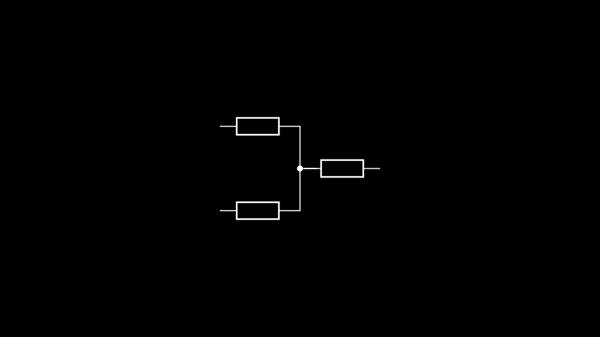
Autoblobbing
Circuit drawing best practice says that intersections of wires should be drawn with
solder blobs. By default, Nodes handle this automatically, in what
manim-eng calls autoblobbing. Let’s take a look at an example.
class AutoblobbingExample(Scene):
    def construct(self):
        r1 = Resistor().shift(UL)
        r2 = Resistor().shift(DL)
        r3 = Resistor().shift(RIGHT)
        n = Node()
        self.add(
            r1, r2, r3, n,
            Wire(r1.right, n.up).attach(),
            Wire(r2.right, n.down).attach(),
            Wire(r3.left, n.right).attach(),
        )
        n.update()
Note
Nodes use updaters to perform autoblobbing, and so in static scenes they need
kicking into gear by manually calling update(). If you’re dealing with more than
one node, the manim.scene.scene.Scene.update_mobjects()
method on scenes can update them all at once.
If you don’t want to use this behaviour, you can pass autoblob=False to the node
constructor or use the disable_autoblobbing() method and use
show_blob() or hide_blob() to manually control whether or not
to display a blob. (Note: these methods disable autoblobbing as well, to prevent there
being two sources of truth on whether a blob should be visible.)
Note that, by default, nodes will display their blob if autoblobbing is disabled in the constructor. If we change the node construction to be
n = Node().hide_blob()
we see the below.

No blob!
Keeping nodes in place using updaters
Nodes provide us with a way to produce complex layouts, but currently we
can’t make them responsive to component movement. That’s where Manim’s updaters come in.
Note
This does not aim to be a comprehensive guide to updaters, as they are a Manim feature and not something introduced by manim-eng. This will only touch on how they can be used to create responsive layouts within manim-eng. If you want to learn more about updaters, Manim’s deep dive page touches on them briefly, and you can also take a look at the entries in its API docs.
Let’s examine the simple example of a potential divider.
class PotentialDivider(Scene):
    def construct(self):
        r1 = Resistor().shift(2 * UP).rotate(0.5 * PI)
        r2 = Resistor().shift(2 * DOWN).rotate(0.5 * PI)
        n = Node().shift(1 * DOWN)
        t = OpenNode().shift(2 * RIGHT + 1 * DOWN)

        self.add(
            r1, r2, n, t,
            Wire(r1.left, n.up).attach(),
            Wire(r2.right, n.down).attach(),
            Wire(n.right, t.left).attach(),
        )
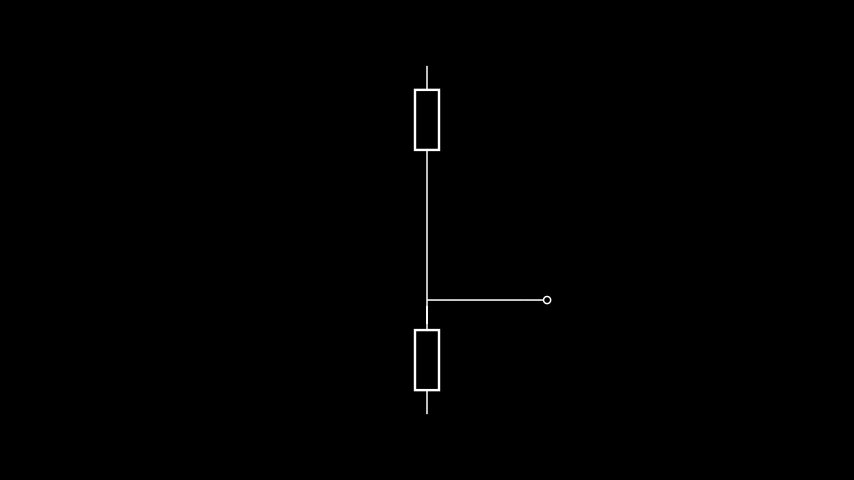
In a somewhat contrived manner, I’ve deliberately placed the open node off-centre. Let’s put that right with an animation. We’ll add the following lines to our scene.
self.play(t.animate.shift(UP))
self.wait()
That looks fine, but it’s a bit annoying that the node and open node are misaligned now. We could of course just move the node as well, but that’s kind of cumbersome. Instead, we’ll add an updater, which will keep the node aligned.
To do this, we’ll add the line below just above the self.add() call.
n.add_updater(lambda mob: mob.align_terminal("right", t.left))
Note that this uses the align_terminal() method, a positioning method
added by manim-eng that allows you to keep terminals of different components aligned
with one another. Using this updater gives us the below.
That looks much better. This example, although simple, hopefully shows the theory of combining nodes and updaters to create responsive layouts.
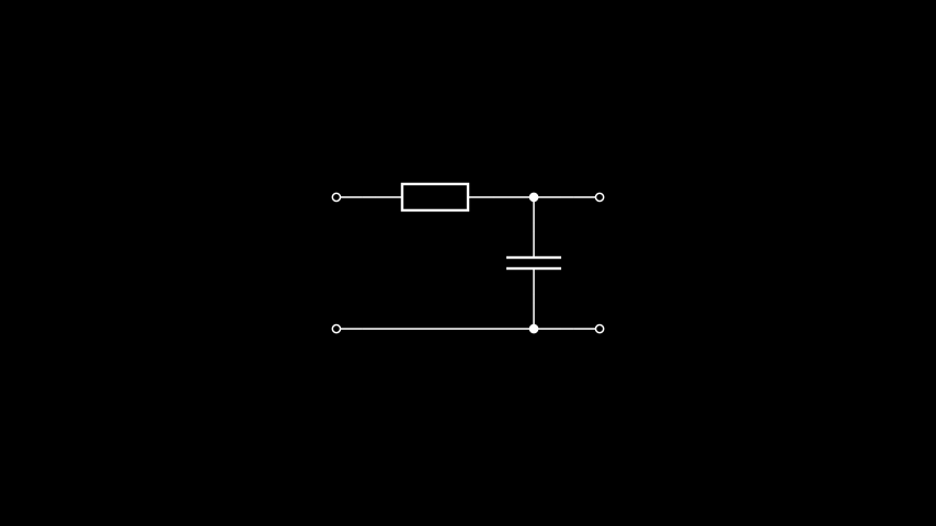
The open node: the other kind of node
The OpenNode acts precisely like a normal node, but with the centre unfilled
and autoblobbing disabled. It is used to represent circuit
terminals (note that this is not referring to the manim-eng concept of component
terminals, but the external connections to a circuit in a circuit diagram. In fact, I
snuck one in in the previous section. For another example,
the below displays a two-port network low-pass filter.
class LowPassFilter(Scene):
    def construct(self):
        in_pwr = OpenNode().shift(UP + 2 * LEFT)
        in_gnd = OpenNode().shift(DOWN + 2 * LEFT)
        out_pwr = OpenNode().shift(UP + 2 * RIGHT)
        out_gnd = OpenNode().shift(DOWN + 2 * RIGHT)
        r = Resistor().shift(UP + 0.5 * LEFT)
        c = Capacitor().shift(RIGHT).rotate(0.5 * PI)
        node_up = Node().shift(UR)
        node_down = Node().shift(DR)

        self.add(
            in_pwr, in_gnd, out_pwr, out_gnd,
            r, c,
            node_up, node_down,
            Wire(in_pwr.right, r.left).attach(),
            Wire(in_gnd.right, node_down.left).attach(),
            Wire(r.right, node_up.left).attach(),
            Wire(node_up.right, out_pwr.left).attach(),
            Wire(node_down.right, out_gnd.left).attach(),
            Wire(node_up.down, c.right).attach(),
            Wire(node_down.up, c.left).attach(),
        )
        self.update_mobjects(0)
Advanced wiring: the ManualWire class
The automatic wire routing is great, but sometimes, you need something custom. In this
case, you have two options. The first is to subclass the WireBase class —
this is particularly good if you want to encode new routing behaviour to use repeatedly.
The other, simpler, method is the ManualWire class. This requires a list of
points at which the wire should have corners, which can be updated later using the
set_corner_points() method if desired. This can be combined with an
updater to make a responsive wire, but if using anything more than trivial logic for
this you probably want to be using the subclassing option above.
Let’s take a look at ManualWire in action. For this we’ll use a simple
‘switchboard’, which aptly demonstrates the main use case of the ManualWire:
it facilitates diagonal wires.
class Switchboard(Scene):
    def construct(self):
        in1 = OpenNode().shift(UP + 2 * LEFT)
        in2 = OpenNode().shift(DOWN + 2 * LEFT)
        out1 = OpenNode().shift(UP + 2 * RIGHT)
        out2 = OpenNode().shift(DOWN + 2 * RIGHT)
        self.add(in1, in2, out1, out2)
        self.add(
            ManualWire(
                in1.right, out2.left, [UP + 0.5 * LEFT, DOWN + 0.5 * RIGHT]
            ).attach(),
            ManualWire(
                in2.right, out1.left, [DOWN + 0.5 * LEFT, UP + 0.5 * RIGHT]
            ).attach(),
        )

In fact, if you just want to connect two terminals directly, you don’t need to specify the list of corner points at all. Let’s look at what this would look like in our switchboard example.
class Switchboard(Scene):
    def construct(self):
        in1 = OpenNode().shift(UP + 2 * LEFT)
        in2 = OpenNode().shift(DOWN + 2 * LEFT)
        out1 = OpenNode().shift(UP + 2 * RIGHT)
        out2 = OpenNode().shift(DOWN + 2 * RIGHT)
        self.add(in1, in2, out1, out2)
        self.add(
            ManualWire(in1.right, out2.left).attach(),
            ManualWire(in2.right, out1.left).attach(),
        )
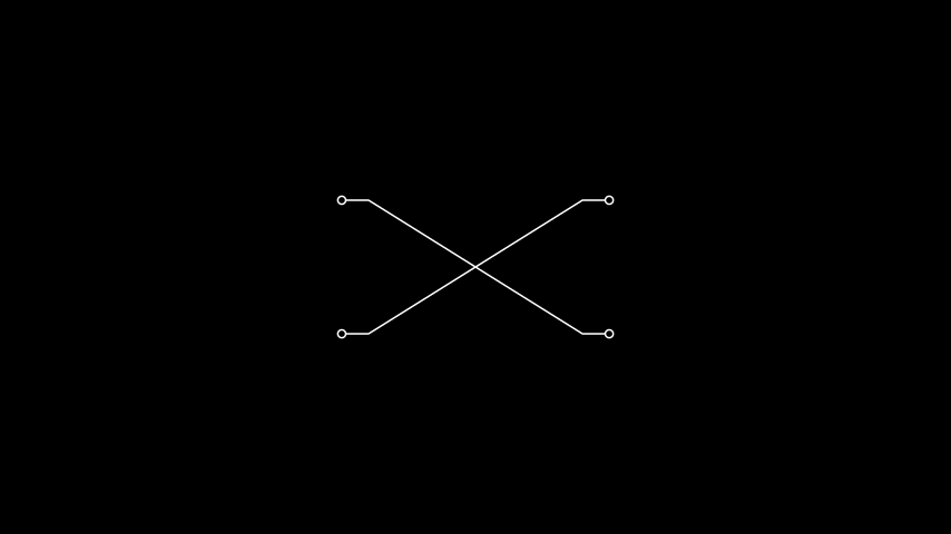
As can be seen above, the wires now go directly from one terminal to another.